 Richard's Blog
Emergency stop: a latch that never releases itself
Key points. IGNIS-8 is a hobby project in the planning phase — no working prototype yet. The emergency stop described here is software: a latched e-stop in the operator terminal and a second, independent latch in the vehicle controller. Both latch on their own trigger sources and both clear only through a deliberate, manual acknowledgement — release held 800 ms, controls neutral, no trigger still active. There is no automatic reset anywhere in the chain. The design also keeps subsystems that do not move the vehicle — the camera gimbal, the sensors, the video streams — live while the drives are released, because a fault is exactly when the operator needs a clear view.
The problem an e-stop has to solve#
An emergency stop that releases when the button is let go is not an emergency stop. The classic failure: the operator presses the mushroom button while holding the stick forward, the drives stop, the operator releases the button to reach for something — and the vehicle resumes immediately, because the stick is still forward. The mechanical mushroom button on IGNIS-8 latches and must be twisted to release. The software mirrors that behaviour, and then goes further.
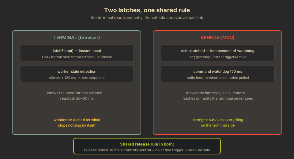
There is a second, less obvious failure that the software has to handle: where the stop lives. The operator terminal is a browser on a handheld. If the emergency stop lived only in the terminal, a dead terminal — a crashed browser, a switched-off handheld, a dead radio link — would stop nothing. The terminal is shouting into a void. The vehicle needs its own decision-making, independent of the terminal, so that it can stop itself when the operator can no longer reach it at all.
That is why the current design has two latches instead of one: a terminal latch that reacts instantly to the operator, and a vehicle latch that survives everything on the terminal side.
Three independent stop mechanisms#
The e-stop is only one of three independent mechanisms, and they are deliberately built to fail differently — no single failure takes out all of them:
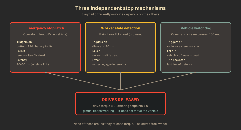
| Mechanism | Triggers on | Fails if |
|---|---|---|
| Emergency stop latch (terminal + vehicle) | Operator intent, battery faults, motor temperature, tip-over, charge connector | Terminal itself is dead |
| Worker stale detection | Main thread blocked (> 120 ms) | Worker itself is dead |
| Vehicle watchdog | Command stream ceases (150 ms) | Vehicle software is dead |
The vehicle watchdog is the backstop: radio loss, terminal crash, closed browser tab, pulled cable — all produce the same observable condition at the vehicle: no more commands. The watchdog does not care which of those occurred.
Why the vehicle needs its own latch#
The watchdog alone is not enough. It is undebounced and clears as soon as a fresh command arrives — which is correct for its job, but wrong for an e-stop. Consider a persistent fault: the battery reports an overcurrent. The watchdog would let the vehicle drive again as soon as the next command tick arrived, because nothing tells it why the stop happened.
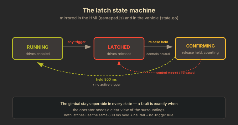
The vehicle therefore runs its own e-stop latch in SystemState, independent of the watchdog. Any trigger source latches it via TriggerEstop, and it stays latched until the acknowledged release path clears it. The release is evaluated backend-side in GetKinematicInput and requires all three of:
- a release source held for
EstopReleaseHold(800 ms), and - the drive setpoints neutral, and
- no trigger source still demanding a stop.
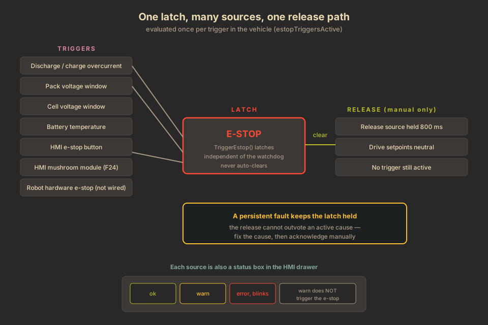
That last condition is the no-automatic-reset rule. The release cannot outvote an active cause: if the battery is still overcurrent, holding the release button changes nothing. Fix the cause, then acknowledge manually. This is what makes the difference between a latch and a mere flag.
One latch, many trigger sources#
Every source that can decide "this vehicle must not move" feeds the same latch. Today these are:
- Discharge overcurrent (current below
-DischargeErrA) - Charge overcurrent (current above
ChargeErrA) - Pack voltage outside the 18.0–25.2 V window
- Any cell outside the 2.5–4.25 V window
- Battery temperature below 0 °C or above 50 °C
- Cell-to-cell delta beyond 50 mV (max − min cell voltage; warning from 30 mV)
- Motor temperature above 70 °C — the hottest MOSFET or rotor temperature across all motors (warning from 50 °C)
- Tip-over — combined tilt above 70 % of the roll limit (warning from 50 %); latches only with a real LiDAR IMU
- Charge connector inserted — a bridge in the charge plug closes a CAROB08 DI channel (
can.carob08_charge_input, e.g.01:0) as long as the plug is in - HMI e-stop button (
estop_trigger = "hmi_button") - HMI mushroom module, F24 (
estop_trigger = "hmi_f24") - Robot hardware e-stop — the wiring point is reserved, not yet wired
The battery sources are evaluated in the BMS task via the shared estopTriggersActive(state) function; motor temperature is the aggregation the control loop already computes (MaxMotorTemp); tip-over derives from the LiDAR IMU attitude against the X-Maxx geometry (roll limit ≈ 61° at half-track 270 mm / COG 150 mm); the charge-connector sense input is read from the CAROB08 DI/DO modules on the BMS bus; the HMI sources reach the vehicle over the control WebSocket as estop_trigger, set by latchEstop in gamepad.js and carried by control_worker.js. A non-empty value latches the vehicle e-stop immediately; clearing it alone never unlatches it.
Every source also appears as a status box in the HMI's e-stop drawer: green when nominal, yellow when outside the warning window, red and blinking when it has crossed the error bound. The HMI never derives a threshold — it only displays what the backend evaluated, so the drawer and the latch cannot disagree.
Why the stop is selective, not total#
An emergency stop on a reconnaissance vehicle has an unusual requirement: it must stop the drive, but not necessarily the mission instruments. IGNIS-8 exists to inspect battery hazards from a safe distance — exactly the situation where the operator most needs a live view of the surroundings.
The design therefore releases only the drive and steering channel. The kinematics input is forced to zeros; drive torque is withheld; steering setpoints are zeroed. Everything that does not move the vehicle stays live:
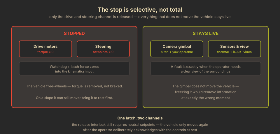
- Camera gimbal — pitch and yaw remain fully operable (D-pad, arrow keys, recenter). The gimbal does not move the vehicle, so it is safe to use, and a view of what went wrong is worth more than a frozen head.
- Sensors and streams — thermal camera, LiDAR, video, telemetry all keep reporting.
This was a deliberate decision, not an oversight. Freezing the gimbal during a fault would remove information at exactly the moment it matters most. The safety analysis documented in docs/safety.md calls this out explicitly: during a fault the view of the surroundings is more valuable than usual.
The stop also arms the drive gate: once a hard failsafe — watchdog timeout or a latched e-stop — has tripped, the drive stays disarmed until the operator explicitly re-arms it. This is the drone-style arm gate covered in the companion post Arming the drive: a fail-safe by default.
Advantages of the current design#
- No automatic reset anywhere. Both latches require a deliberate, held acknowledgement with the controls at rest. A momentary stray press of the release cannot clear anything, and a persistent fault holds the vehicle stopped until it is actually fixed.
- Survives a dead link. Because the vehicle latches independently, a dead terminal, a crashed browser or a lost radio link leaves the vehicle holding its stop — the terminal latch alone could not do that.
- Sources the latch, not the operator. Battery and motor faults latch the vehicle without any operator involvement, and the HMI cannot re-arm the vehicle while a cause is still active.
- Charging is physically excluded. The charge connector is a hard trigger: while the plug is in, the drives cannot run — a condition that operator intent alone must not override.
- Simulation never stops the vehicle. A simulated LiDAR attitude is labelled ADVISORY in the drawer and can colour the box, but can never latch — a synthetic slope must not stop the vehicle.
- Single evaluation, single truth.
estopTriggersActiveis shared by the BMS task (latching) and the release logic (blocking), so both sides see the same conditions by construction. - Per-source visibility. The drawer shows which source tripped and how far outside its window it is — the operator diagnoses instead of guessing.
- Selective stop. The gimbal and sensors stay live, which is the entire point of a reconnaissance platform.
- Warning is decoupled from stopping. Warning levels colour boxes yellow but never trigger the e-stop, so the operator is informed early without the vehicle stopping on every excursion.
Disadvantages and honest limits#
- The e-stop is not faster than the watchdog when the link is down. If the radio is already dead, the mushroom button changes nothing at the vehicle — the terminal is shouting into a void, and the vehicle's own watchdog is the backstop. For a ~1.3 km/h, 20–35 kg vehicle that is acceptable; for anything faster or heavier it would need an independent radio kill channel.
- Two latches to keep consistent. The terminal latch and the vehicle latch must agree on the release rule. Today both use the same 800 ms hold + neutral + no-trigger logic, but the duplication is a real maintenance surface — a change to one must be mirrored in the other.
- No braking. All three mechanisms remove torque; none brakes. The vehicle free-wheels and can still move on a slope. This is a deliberate omission — active braking through the drive motors would need a controlled deceleration ramp, and an uncontrolled one could tip a vehicle whose centre of mass sits above the wheel axes.
- Not a certified safety system. There is no ISO 13849 Performance Level and no IEC 61508 SIL rating. These are engineering measures for a remotely operated research vehicle, proportionate to its energy and environment — not a substitute for a rated safety chain.
- The tip-over threshold scales with the assumed COG height. The 0.15 m centre-of-gravity height is an estimate; a higher real COG would tip earlier than the trigger assumes. It is the one figure worth measuring before the first real drive.
- The robot hardware e-stop is not wired yet. The source, the drawer box and the release input exist, but the physical connection on the robot is still to be built.
What the operator sees#
The HMI's e-stop drawer renders the whole picture as a mindmap: trigger sources on the left, the latch state in the centre, release sources on the right. Current, voltage, temperature, the cell-to-cell delta, motor temperature and the tip-over are combined boxes with the live value on the left and the warn/error limits on the right; cells, the charge connector, the HMI button, the F24 source and the robot input are single boxes. The tip-over box carries an ADVISORY label while the LiDAR runs simulated. A fault blinks red; the centre box reads LATCHED with the instruction "hold reset to clear".
Release comes from the same place as the latch: the e-stop module's reset button (F23) or the Enter key, held with the controls released. The gamepad START button is deliberately not mapped to the release — the release belongs on the same module as the latch, not on a stray gamepad press.
Where the design goes from here#
The trigger set is essentially complete: the battery faults that motivated the e-stop in the first place, the operator-side triggers, the charge connector, motor temperature and a hardware-gated tip-over. What remains is mostly physical rather than logical. The on-board computer temperature and the Wi-Fi link stay warning-level by design — they are situational reports with real kernel data sources now, not e-stop sources, because a hot board or a weak radio must inform the operator without stopping the vehicle. The robot-side hardware e-stop input exists in the software and the drawer, but the physical connection on the robot is still to be built. And the one figure that would genuinely tighten the safety envelope is the real centre-of-gravity height — measured on the actual chassis, it would move every tip-over threshold off its current assumption.
The short version: the e-stop is implemented the way it is because a stop that clears by itself is not a stop, and because on a remotely operated vehicle the stop must survive the link dying. The price is two latches to keep consistent, no braking, and an honest ceiling — this is engineering, not certification. In exchange the vehicle gets a stop that holds until the cause is gone, per-source visibility of what tripped it, and a camera that keeps looking at exactly the moment the operator most needs eyes.