Overview / Scope
I'm currently working on a mount for astrophotography which uses strainwave gears.
Once finished and working, I will publish all needed files for public use.
Scope of use / needs
The planned use case and needs of this mount are:
- Focal ranges of up to 1500mm → Static load of up to 15kg without counter weight
- Perfect tracking for focal length of around 650mm and below as I'm mostly interested in DSOs.
- Ability for autoguiding and dithering
- Use it either stationary on a pier or in the field (transportation by car) on a photo tripod (altough with reduced load!)
- Single supply voltage of 12V
- Single USB port for connection to computer (Mounted on RA housing)
- Port for focusser
Mechanics
The complete mechanical assembly was be designed using Fusion 360. I followed the basic mechanical principle of “form follows function”.
I am using lasercut 10mm aluminium for the load bearing parts.
All parts which are more than a simple 2D contour are 3D printed and will be designed to be printed with a standard off-the-shelf printer like the Ender 3.
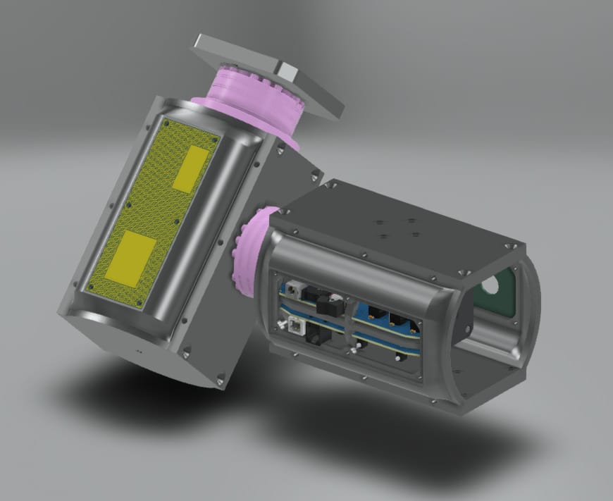
Motor mount and adapter
The motor mount mount holds the stepper with it's small strainwave gear in place. It also must widthstand the grease of the main strainwave gear.
The adapter to transmit the power from the stepper to the main gear is planned to be either turned on a lathe or 3D printed out of metal.
Electronics
The electronics is based on a Teensy v4.1 which will run OnStepX.
All PCBs will be created with EasyEDA, so anyone can copy them.
Accuracy
The tracking accuracy the mount has to be able to handle is calculated with the following script.
Calculated with the OnStep-Config we can reach down to 0.14 arcsec/pixel.
###############################################################################
#   DO WHAT THE FUCK YOU WANT TO PUBLIC LICENSE
#                Version 2, December 2004
#
# Copyright (C) 2004 Sam Hocevar
# 14 rue de Plaisance, 75014 Paris, France
# Everyone is permitted to copy and distribute verbatim or modified
# copies of this license document, and changing it is allowed as long
# as the name is changed.
#
#       DO WHAT THE FUCK YOU WANT TO PUBLIC LICENSE
# TERMS AND CONDITIONS FOR COPYING, DISTRIBUTION AND MODIFICATION
#
# 0. You just DO WHAT THE FUCK YOU WANT TO.
#

###############################################################################
# Use this script, if you are to lazy to use the formulas 😉

###############################################################################
# Enter optical data of equipment
focallength=150
reducer=1

# Canon R6
sensor_width_mm=35.9
sensor_width_pxl=5492

# Raspi HQ Camera
#sensor_width_mm=6.287
#sensor_width_pxl=4056

#Dwarf III
#sensor_width_mm=7.35
#sensor_width_pxl=3840

cropfactor=36.0/sensor_width_mm

pixel_size= (sensor_width_mm / sensor_width_pxl) * 1000.0 # pixel size in µm
fov_pixel=((pixel_size / (focallength*reducer)) * 202.265) #arcsec/pixel
fieldofview = fov_pixel * sensor_width_pxl / 3600 # fov in degree
###############################################################################

print("Focal length telescope:     %.2f mm" % (focallength))
print("Reducer factor:             %.2f" % (reducer))
print("Focal length optical train: %.2f mm" % (focallength*reducer*cropfactor))
print("Crop factor:                %.3f" % (cropfactor))
print("Pixel size:                 %.2f µm" % (pixel_size))
print("FOV:                        %.2f degree" % (fieldofview))
print("FOV/pixel:                  %.2f arcsec/pixel" % (fov_pixel))
print("Minimal tracking accuracy:  0.14 arcsec/pixel")
Combined together we get the following formula:
With the highest planned focal length, we can calculate the FOV per pixel:
\( FOV_{pixel}=\frac{\frac{36mm}{5492}\cdot{}1000}{1500mm\cdot{}1}\cdot{}202.265=0.88 [arcsec/pixel] \)
Combined with the known 0.14 arcsec/pixel we can now be assured that mount can handle this focal length. Even a much higher focal length of 6000mm would result in a FOV of 0.22 arcsec/pixel which it should be able to handle. No guarantees for this though!