
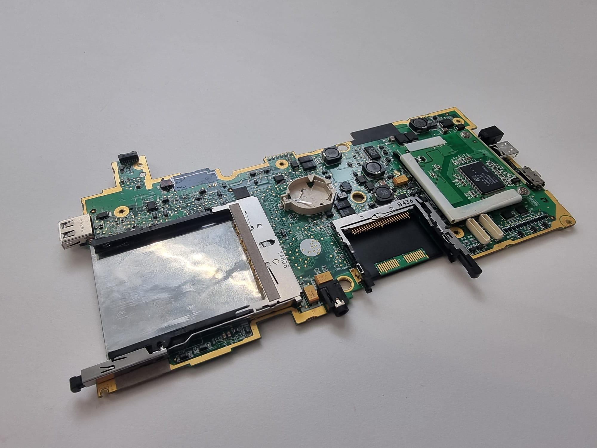
The next step after reverse engineering the keyboard was, of course, designing a new mainboard. For that, I depopulated the old mainboard scanned both sides.

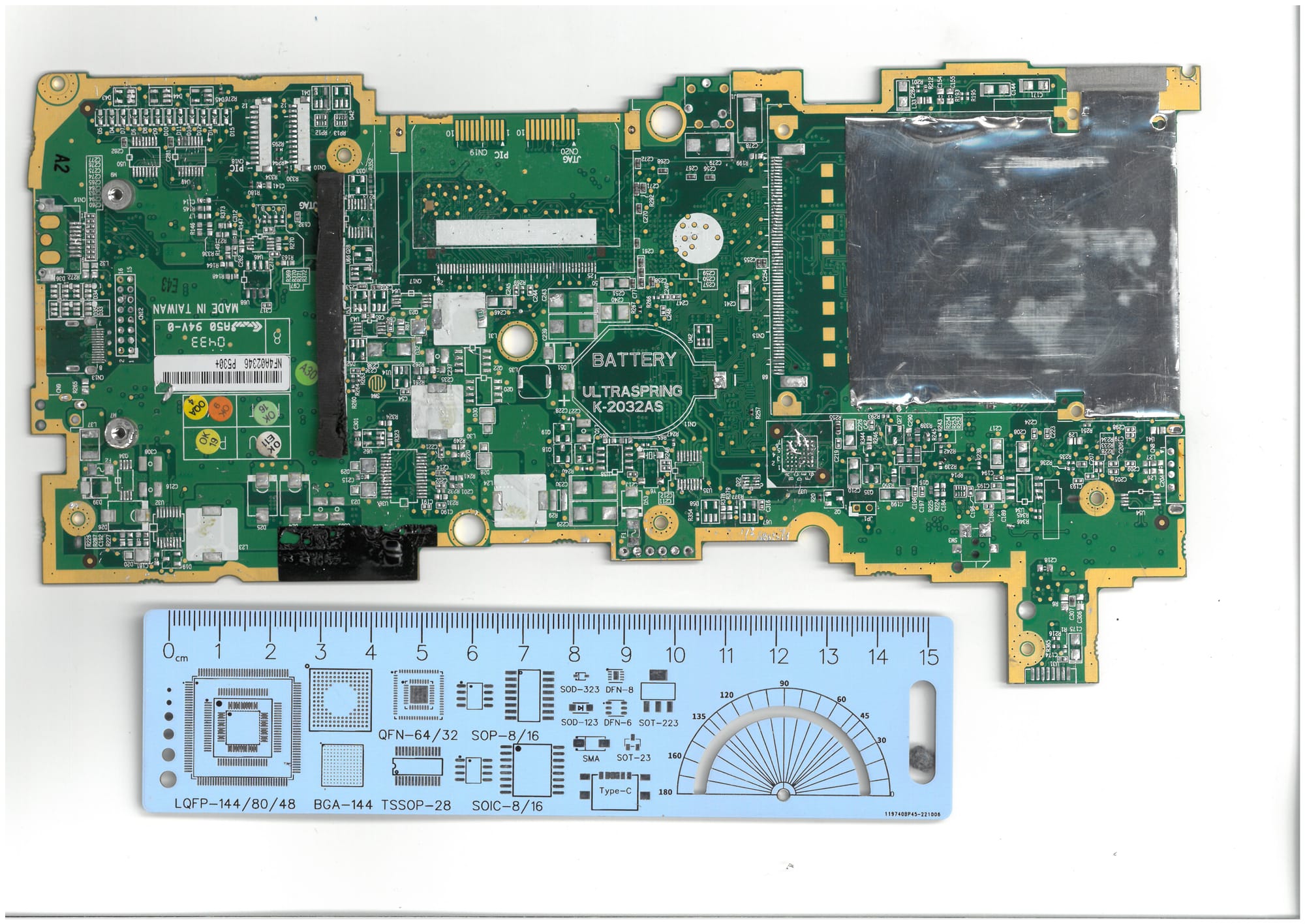
I took care to scan the PCB together with a rule, so I could create a proper sized DXF file. This was then imported into Easy EDA Pro, which I wanted to use as PCB editor. I switched from KiCAD to Easy EDA especially to make it easy for other hackers to go forward with my work as easy as possible. In this way you don't need to create your own BOM and anything else, just open the project and order the files. The project contains all sideprojects I needed to come up with to have a working system.
During this work, I encountered the question regarding the SSD, which I already published in a different post.
In the following image you can see the intermediate design with a m.2 SSD.
I was finished with part placement, but had a long way to go with routing. The routing is pretty rough, but should do the trick (initially!). Keep in mind, that this is planned as a working prototype, but I want to redo the layout, as I found some issues after ordering. These need to be solved by some small wire patches.
Most important is a missing I2C connection the battery, which will be used for a BQ40Z50-R1 battery fuel gauge residing in the battery.
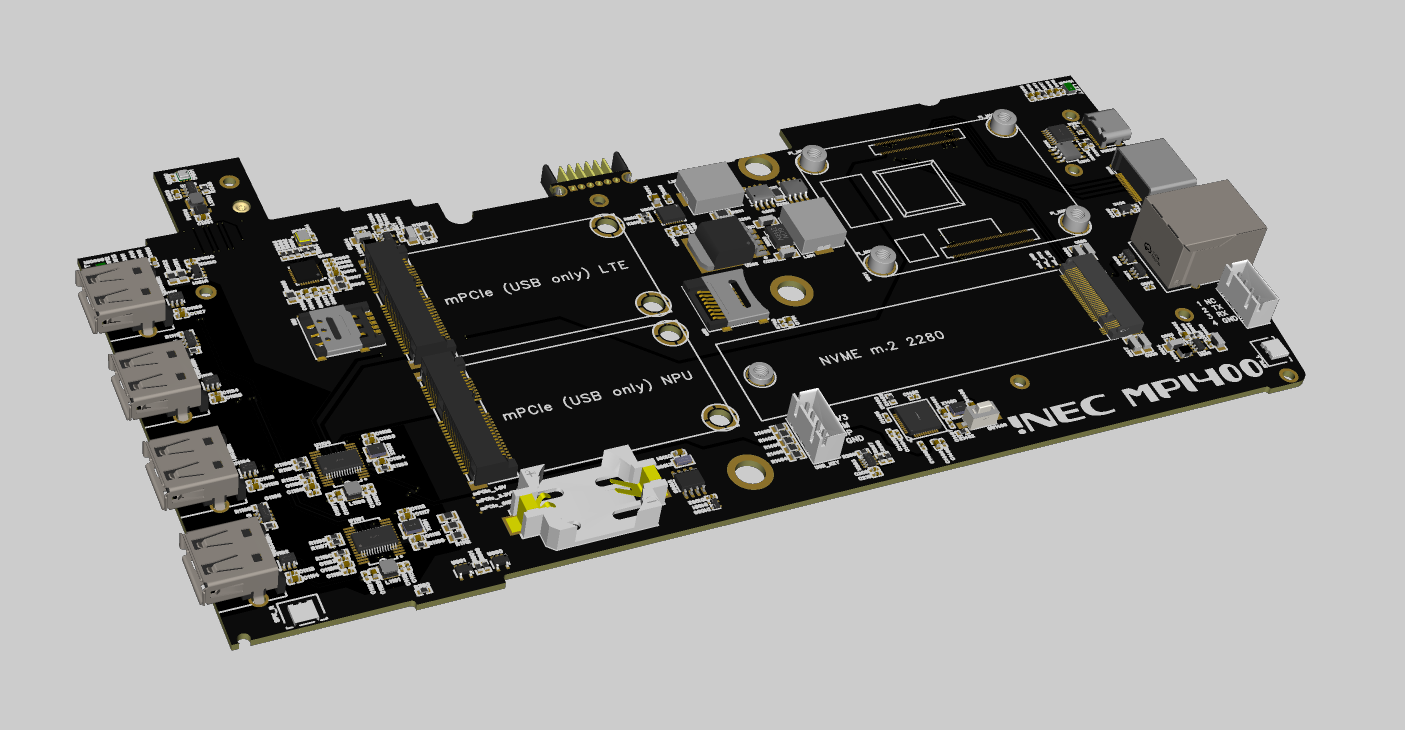
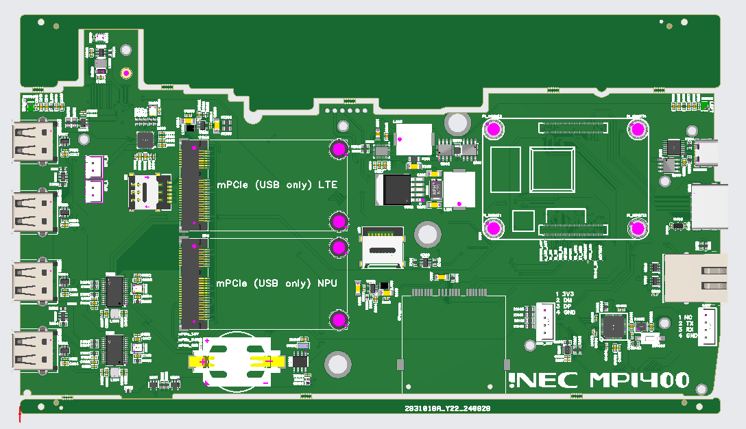
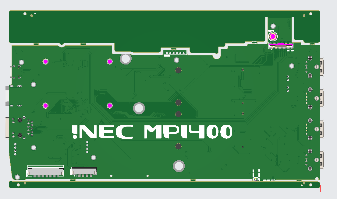
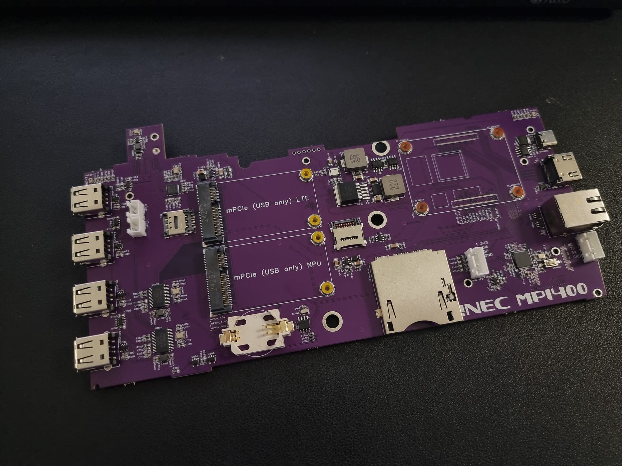
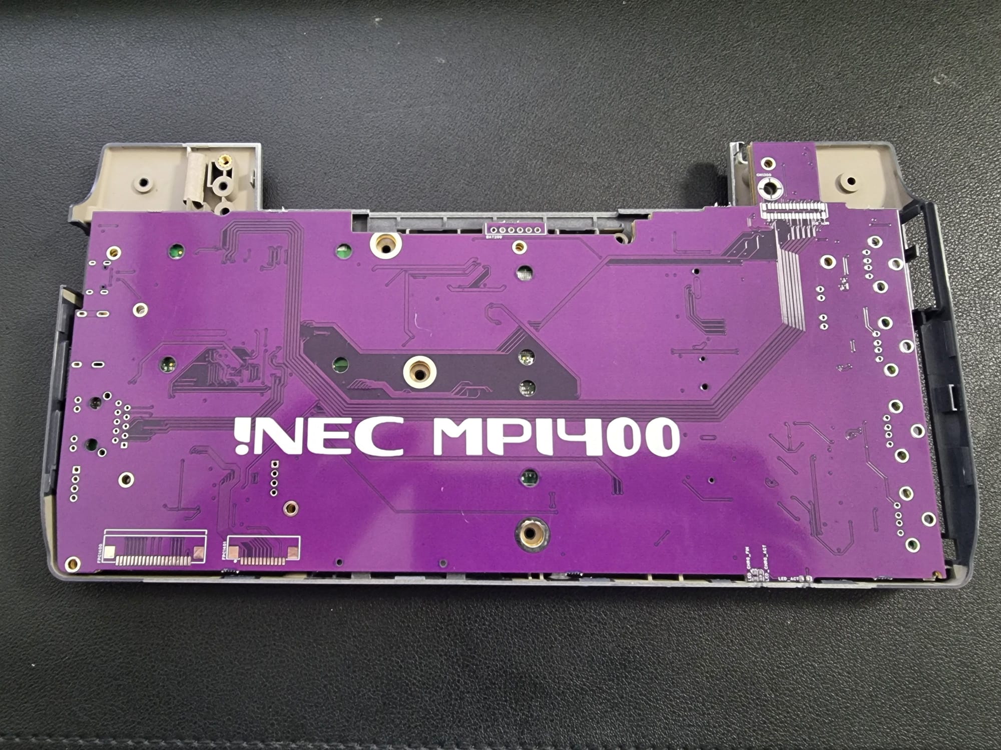
The following two images show the current and ordered state of the PCBs - already containing the CFexpress slot, which was planned roughly in the spot of the CF slot.
After the tedious job of drawing the schematic and layouting the PCB, I finally ordered it.
Besides the connectors it actually fits pretty great in the housing!
But the connectors require a 3D printed bottom shell of the housing anyway.
Also all of the white pin headers need to be swapped with the proper versions and
might be left away as they are only needed for debugging.
Now I need some spare time to get the missing headers soldered and try to get a CM4 running on the mainboard.